
Restaurant solutions
Restaurant ventilation and air conditioning
The kitchen, dining area, wood-fired grill and food preparation rooms require different engineering solutions. SM Systems designs and installs restaurant ventilation and air conditioning to suit cooking processes, layout, available capacity and future maintenance.
People, cookers, ovens, extract canopies and air conditioners all operate simultaneously in a restaurant. Guests expect a comfortable temperature, chefs need suitable working conditions, and the owner needs a system with predictable costs. Reconciling these requirements is particularly important during refurbishment: some equipment is already installed, space for ductwork is limited, and electrical capacity may be insufficient.
The following sections cover the main engineering solutions for restaurants: dining area ventilation, local kitchen extraction, make-up air supply, open kitchens, wood-fired equipment, exhaust air treatment, refurbishment and air conditioning of the supply air. The system configuration is determined by cooking processes, layout, operating hours, available resources and the conditions at the premises.
Planning an opening or refurbishment? Send us a floor plan, a list of kitchen equipment and the available electrical capacity — we will discuss the system configuration and sequence of work.
Are the premises suitable for a restaurant?
The engineering suitability of the premises should be checked before signing a lease, approving the layout or ordering kitchen equipment. The kitchen concept may prove incompatible with the available shafts, utility capacities or air discharge arrangements, and remedial work after fit-out usually requires changes to related designs.
Before design begins, check:
- whether a separate kitchen extract route and a permissible discharge location can be provided;
- whether a route to the roof is possible and shafts, external routes and equipment can be agreed with the building owner;
- space for a supply air handling unit, fans, attenuators and air treatment equipment;
- the source of make-up air for kitchen extraction;
- available electrical, gas and heating capacity;
- the ability to heat and cool outdoor air under design conditions;
- water supply, sewerage and drainage for equipment that requires them;
- fire protection for ducts, shafts and penetrations through building structures;
- maintenance access routes, inspection openings and provision for replacing large equipment;
- limits on noise, vibration and loads on the roof and structures;
- the position of neighbouring windows, balconies, air intakes, entrances and outdoor seating areas.
Requirements for restaurant systems and their location are checked against the applicable Ukrainian regulations, including DBN V.2.2-25:2009, and the conditions of the individual building.
Warning signs of unsuitable premises
- the establishment is in a residential building, but there is no route to the roof;
- the owner prohibits external shafts or rooftop equipment;
- the kitchen processes are still changing, but the ventilation has already been ordered;
- ceiling designs have been approved without space for ductwork and access hatches;
- the electrical capacity is only sufficient for the kitchen equipment;
- open windows and doors are proposed as the source of make-up air for extraction;
- the filters, fans and grease extract duct cannot be serviced;
- the discharge point is close to windows or an air intake.
In these circumstances, an engineering concept is developed first. Only then can the cost be assessed and the suitability of the premises for the planned kitchen format determined.
Which system does each type of establishment need?
The type of establishment helps frame the initial questions, but does not replace an analysis of the kitchen processes, operating hours and building.
| Format | Basic solution | What to check |
|---|---|---|
| Coffee shop without a hot kitchen | General ventilation for the seating area and local extraction from equipment that generates heat or steam | The actual equipment list, dishwasher, operating hours and cooling requirements |
| Café with light cooking | Dining area ventilation, local extraction above cooking equipment and a planned make-up air supply | The menu, simultaneous equipment operation, discharge location and available power capacity |
| Full-service restaurant | Separate solutions for the dining area and kitchen, local extract hoods, conditioned supply air, air conditioning and controls | All kitchen processes, air balance between zones, load profiles, noise and maintenance access |
| Open kitchen | Local capture and controlled airflow from the dining area towards the kitchen | Cross-draughts, the service pass, walkways, diffuser positions and actual capture performance |
| Bakery | Local and general extraction, supply air conditioning and, where required, a full fresh-air system | Heat and steam from ovens, extract air contamination, work areas and seasonal operating modes |
| Charcoal grill, Josper or wood-fired oven | A dedicated extract system, specialist filtration, fire protection and operational monitoring | Fuel type, temperature, sparks, grease deposits, fire suppression and cleaning access |
| Food hall or multiple tenants | Shared infrastructure with defined capacity limits and separate tenant connections | Boundaries of responsibility, spare capacity, air balance during simultaneous operation and utility metering |
| Restaurant in a residential building | Dedicated systems for the establishment, noise control and a properly justified discharge arrangement | The route above roof level, neighbouring windows, shafts, vibration, odours and approval from the property owner |
The type of establishment alone does not determine the system. Two coffee shops may have different requirements if one only reheats pastries while the other prepares hot meals, uses a dishwasher and operates throughout the day.
Kitchen and dining area: a shared air balance, different tasks
Outdoor air, heating and cooling requirements are determined for the dining area. In the kitchen, emissions from cooking equipment add heat, steam and cooking effluent. These must be captured at source. Kitchen extraction is coordinated with the supply air and air transfer between zones: the extracted volume must be replaced. This principle is explained in detail in Design Guide 2: Optimizing Makeup Air.
Restaurant ventilation design therefore starts with the kitchen layout and processes. Where is the grill? Will the kitchen be open? Where is the service pass? Which rooms operate before the dining area opens? Will production increase after refurbishment? The answers determine the system configuration and help avoid costly changes after the finishes are complete.
| Area of the establishment | What needs to be addressed | Example solution |
|---|---|---|
| Dining area | Outdoor air supply, temperature and guest comfort | Enthalpy recovery and ducted air conditioning for a separate floor |
| Cooking line | Local capture and make-up air for extraction | Hoods with a controlled perimeter air supply |
| Grill or wood-fired oven | Specialist extraction and maintenance access | Water scrubber in the extract system |
| Open kitchen | Limiting the transfer of kitchen air into the dining area | Successive supply and extract zones, with an air curtain at the service pass |
| Food preparation rooms | Ventilation suited to the processes and staff working conditions | Separate full fresh-air systems and local air conditioning |
| Bakery | Supply air conditioning and airflow management | Full fresh-air system with DX heating and cooling |
Equipment and ventilation arrangement options are presented in the ventilation systems section.
The kitchen is usually maintained at a slightly lower pressure than the dining area so that air moves from cleaner to more contaminated zones. Some conditioned air from the dining area can be deliberately transferred to the kitchen, but its volume must be coordinated with dining area ventilation, kitchen extraction and airflow through entrances and corridors.
Excessive negative pressure is also a mistake. It makes doors harder to open, draws outdoor air through entrances and gaps, creates draughts and can disrupt fuel-burning equipment. Strong cross-draughts near a hood impair capture. There is no universal percentage for transfer or make-up air: the balance is calculated and checked after installation.
How airflow rates are determined
Kitchen extraction is not sized solely by floor area or a universal air change rate. Calculations start with the emission sources and the conditions in which the hood must reliably capture the plume.
- Compile a list of kitchen equipment.
- Account for power ratings, fuel type and operating patterns.
- Determine emissions of heat, steam, grease, smoke and combustion products.
- Select the hood type, dimensions and position.
- Calculate the airflow rate for capture and containment.
- Calculate the make-up air requirement.
- Check the air balance across the kitchen, dining area, entrances and corridors.
- Calculate heating and cooling requirements.
- Determine filtration, controls and fire response sequences.
- Verify performance on site under actual load conditions.
Excessive extraction does not compensate for incorrect hood geometry or positioning, but it does increase the heating and cooling capacity required for supply air. Insufficient extraction allows steam, grease and odours to escape beyond the hood. The aim of the calculation is reliable capture at a justified airflow rate.
The relationship between the hood, make-up air and capture testing is highlighted in ASHRAE Handbook: Kitchen Ventilation and the BESA DW/172 specification. International publications are used as engineering guidance alongside the requirements applicable to the specific site in Ukraine.
Heat recovery in the dining area: a two-storey restaurant example
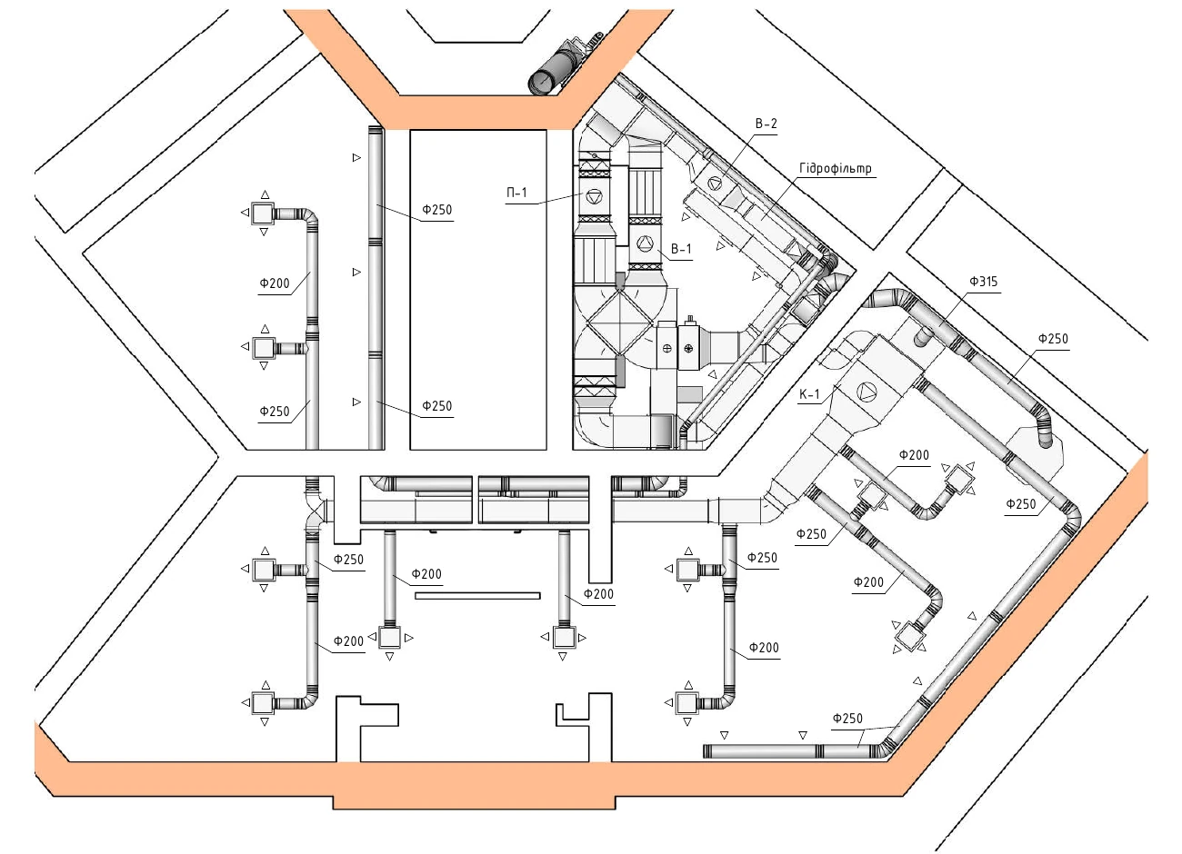
At one restaurant serving Ukrainian cuisine, the first floor was used entirely for guest seating, with no cooking on that floor. Mitsubishi Electric supply and extract ventilation equipment with enthalpy recovery and separate ducted air conditioning was installed for this floor.
Operating experience at this site showed that the selected system helped maintain more comfortable humidity in winter and reduced the need to heat outdoor air. The adopted arrangement did not require additional reheating after the heat recovery unit; preheating was provided for very low outdoor temperatures. This is a feature of this particular solution, with its specific loads and operating conditions.
A wood-fired oven operated on the ground floor. Separate supply and extract systems were installed here, along with a water scrubber, and central cooling was delivered through the supply air. Semi-finished food products were prepared in the basement, which had its own full fresh-air ventilation and local air conditioning to account for the high density of staff.
This resulted in three different arrangements within one restaurant. The dining floor received a heat recovery solution; the floor with the oven received equipment suited to its cooking processes; and the production basement received a separate air supply. For the client, this meant systems selected for the actual purpose of each zone.
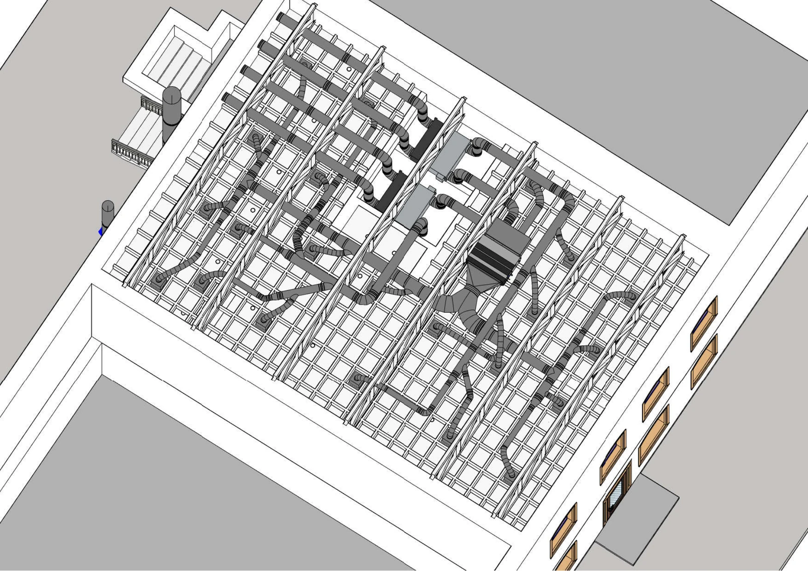
Project example: Two-storey restaurant, approximately 600 m².
Restaurant dining area air conditioning
Air conditioning for the dining area is sized according to guest numbers, equipment, lighting, solar gains and heat from the supply air. Air temperature and jet direction are checked at seating positions, not just at the wall sensor.
The dining area and kitchen have different loads and operating patterns. Dining area cooling does not replace make-up air for kitchen extraction: these systems are coordinated through the air balance to prevent odours reaching guests. Independent controls are provided for banquet areas, bars and separate dining rooms where occupancy and operating hours differ.
The choice between a ducted system, VRF or another cooling source is made after calculations and coordination with the architecture, acoustics and maintenance access. See air conditioning systems and design scope.
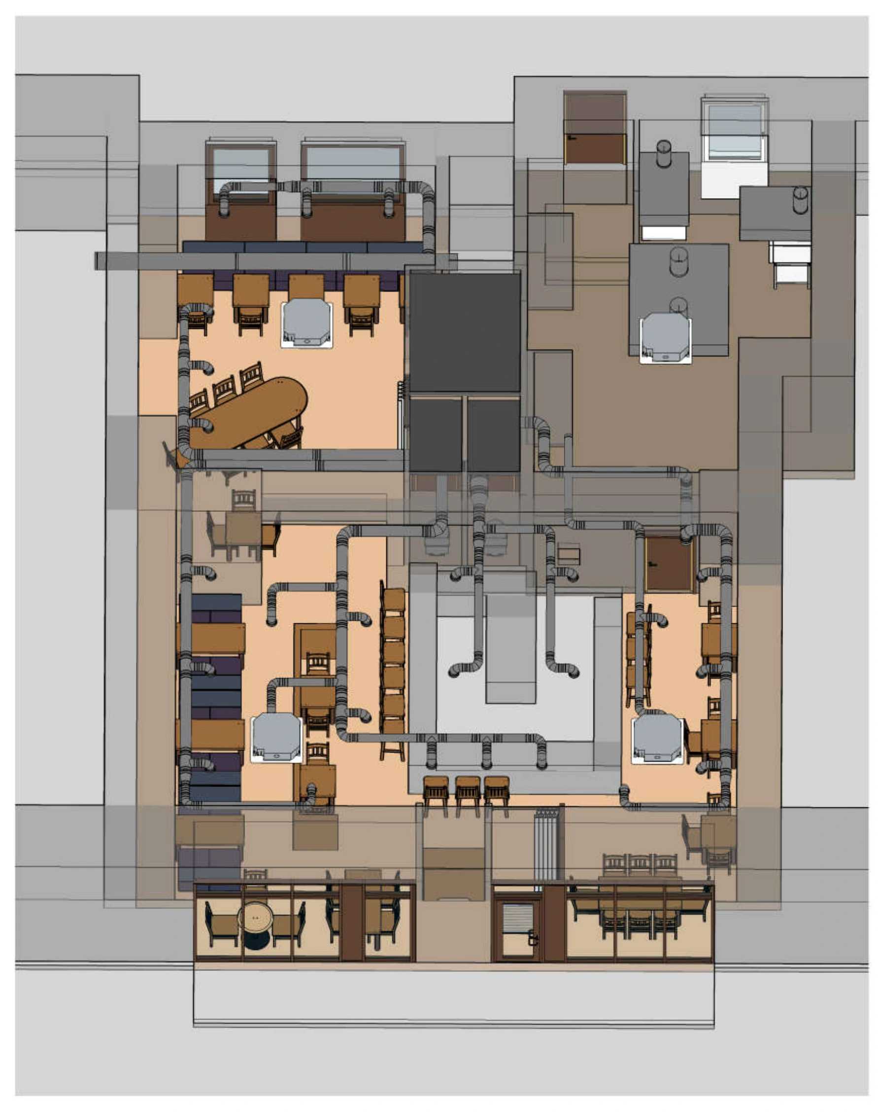
Wood-fired grill: extraction with a water scrubber and cleaning access
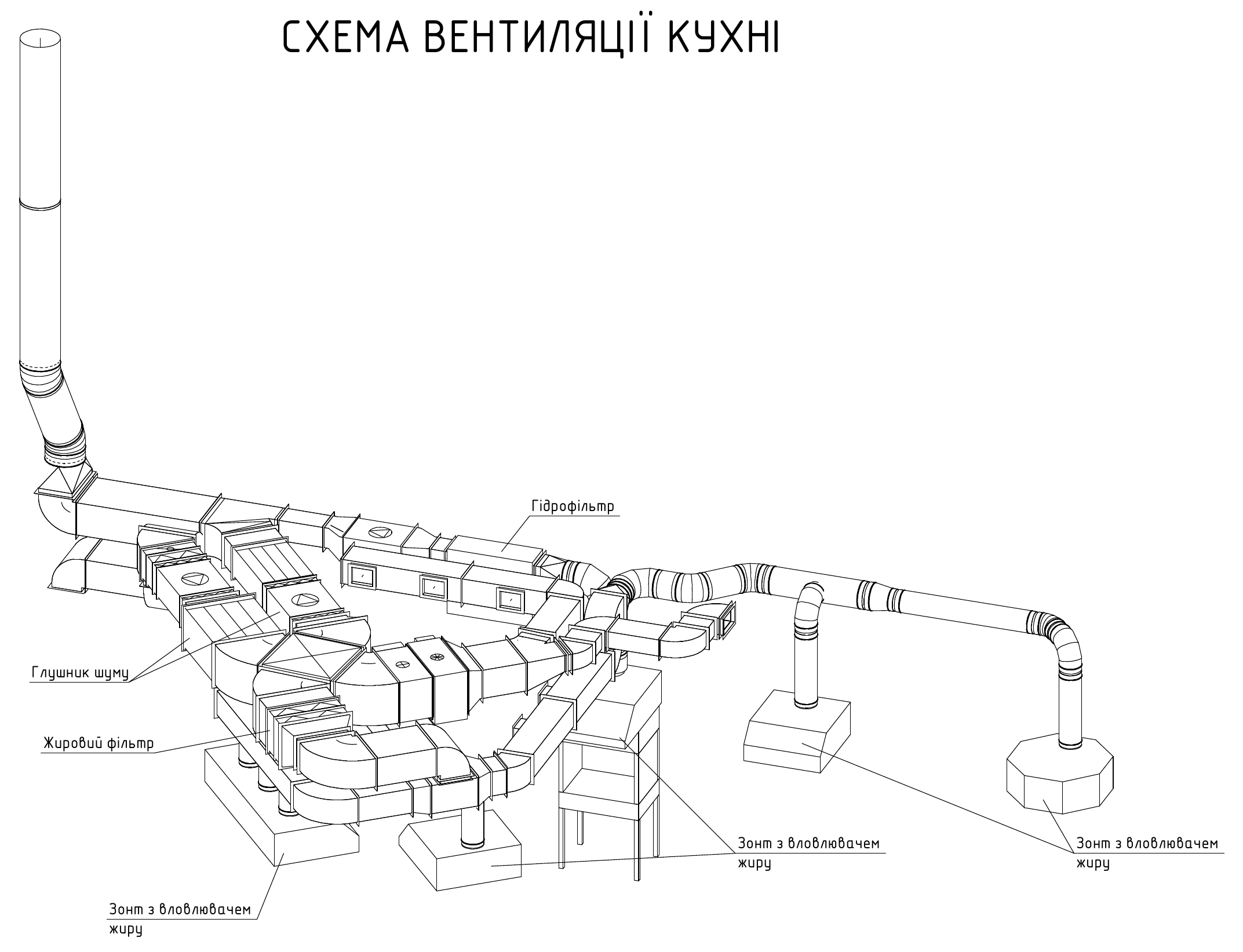
A restaurant serving Georgian cuisine combined heat recovery ventilation, central cooling and separate local extract systems. The wood-fired grill required particular attention. A water scrubber was installed in its extract system, and the hood and ductwork up to the fan were made of steel.
The purpose of the water scrubber in this solution was to reduce sparks carried in the airflow. During operation, the team noted its effective performance, while regular flushing, cleaning and a serviceable pump remained essential. Sparks, deposits and extract system maintenance for solid-fuel equipment are addressed separately in ASHRAE Handbook: Kitchen Ventilation. A water scrubber is part of the technical solution; its presence alone does not guarantee fire safety.
A key requirement is to allocate space for this equipment at the planning stage. In this solution, it was important to position the water scrubber close to the hood while retaining maintenance access. The exact position is coordinated with the system design and equipment documentation.
Similar coordination was needed at a restaurant serving Ukrainian cuisine, where the water scrubber and extract components were integrated into the wood-fired oven arrangement. Outlets, connections, dimensions and service access sides were agreed with the designers. This work determines how conveniently the system can be operated once the interior is complete.
A full section on fire safety for wood-fired equipment is provided at the end of this article.
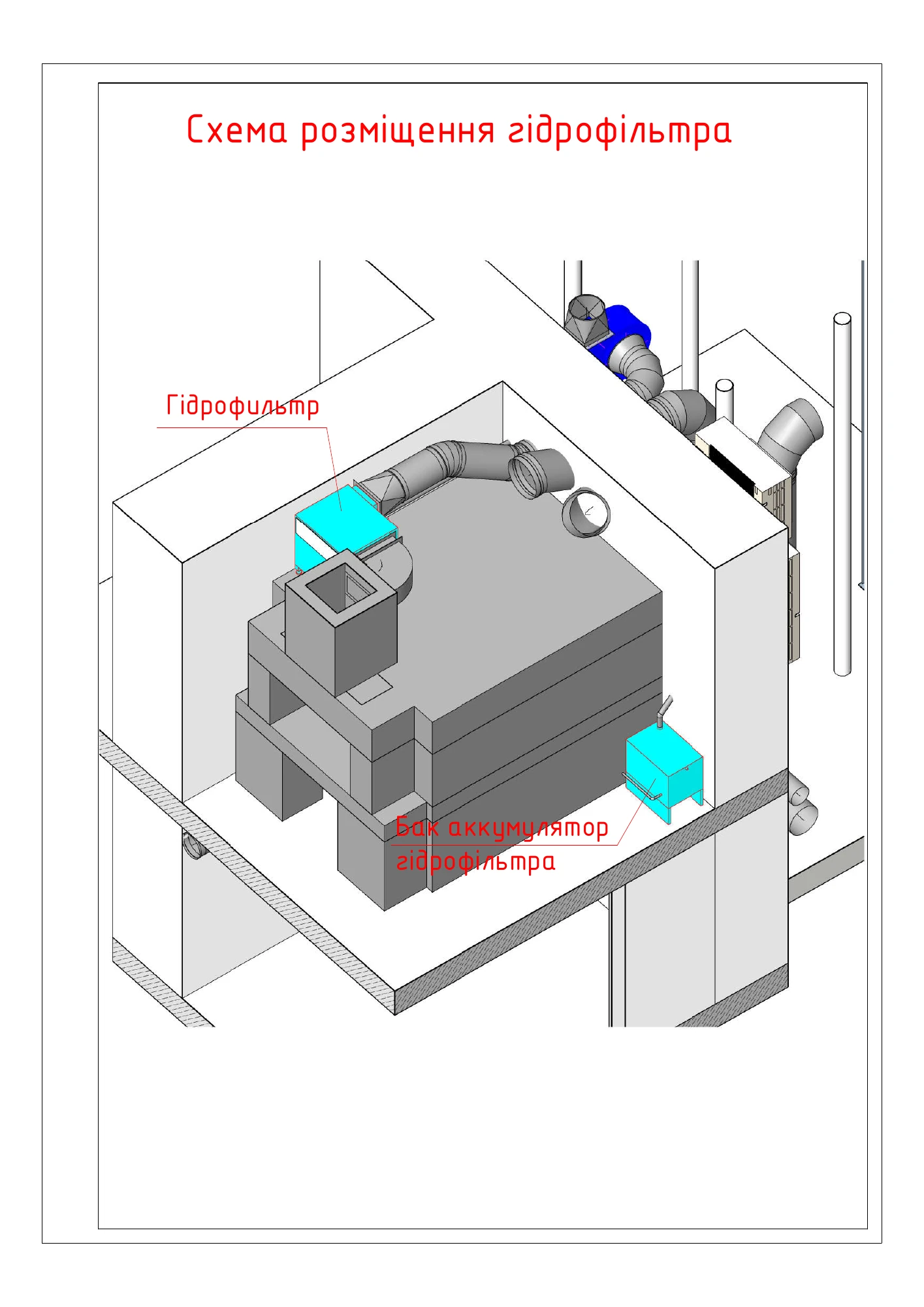
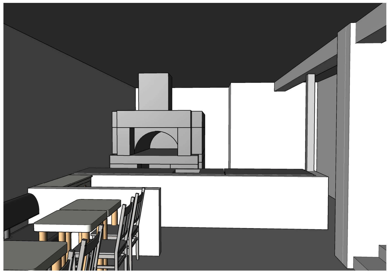
Project example: Restaurant with a wood-fired grill, approximately 300 m².
When electrical capacity is limited: local air supply at the hoods
During a restaurant refurbishment and extension, the client wanted to retain the existing air conditioning and move towards more energy-efficient solutions. The old ventilation systems had no heat recovery, the heat supply was unreliable, and there was insufficient electrical capacity to heat the supply air in winter.
One solution was specially designed extract hoods with a slotted perimeter air supply. Part of the supply air was directed straight into the hood capture zone. At this site, air was supplied locally at approximately +10 °C, with its movement coordinated with the extraction and thermal plume from the cooker. This temperature refers to the air supplied near the hood; conditions in the staff working zone are considered separately.
This solution reduced the heating requirement for that portion of the air. Operating experience showed a substantial reduction in costs following the refurbishment. For each new project, the suitability of this approach is checked against the hood design, supply airflow rate and direction.
Directed air jets near hoods are also used in specialist factory-made solutions to improve capture. One example of this principle is Halton Capture Jet. This is a technical explanation of the approach; the project described is not identified as a Halton system.
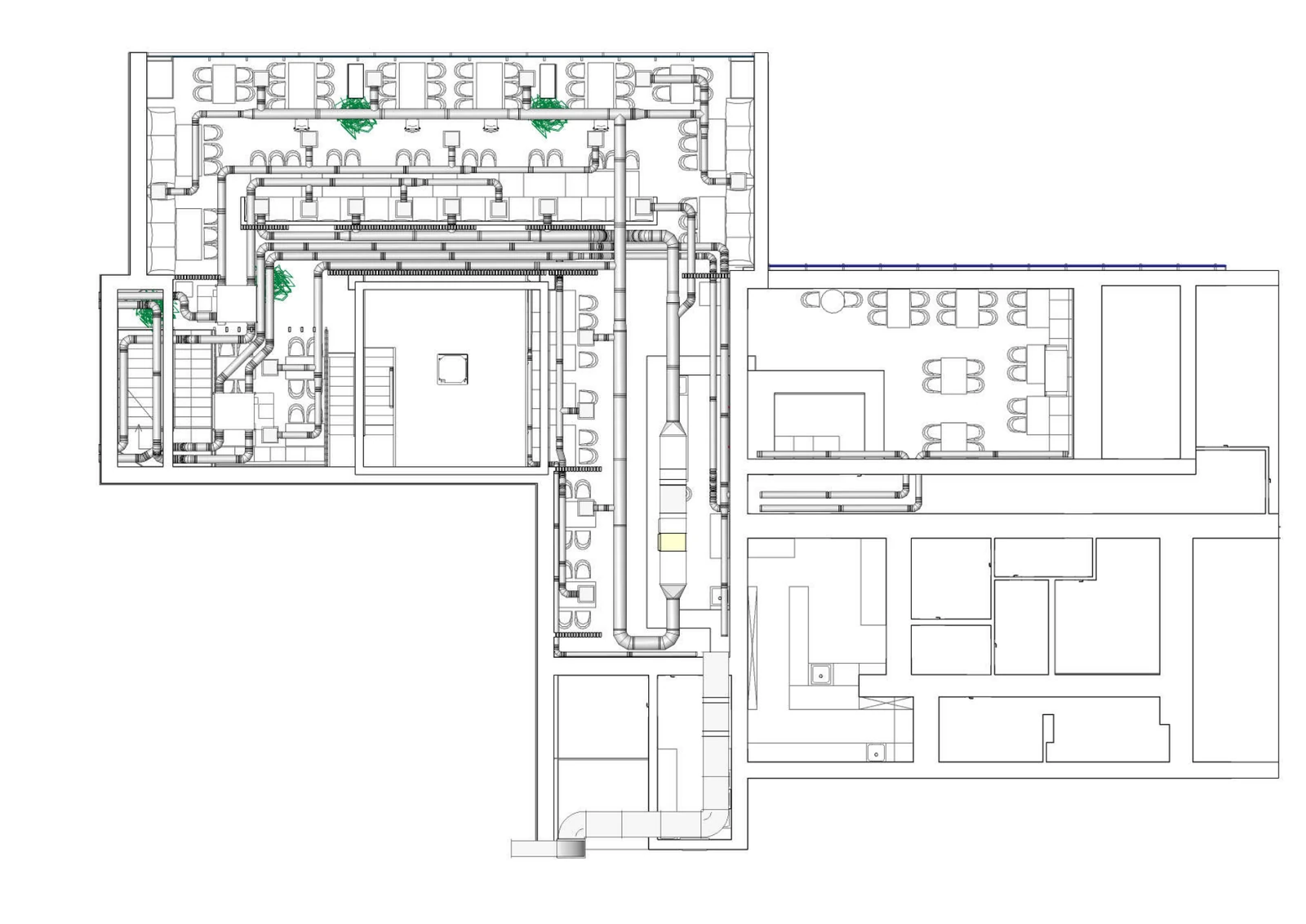
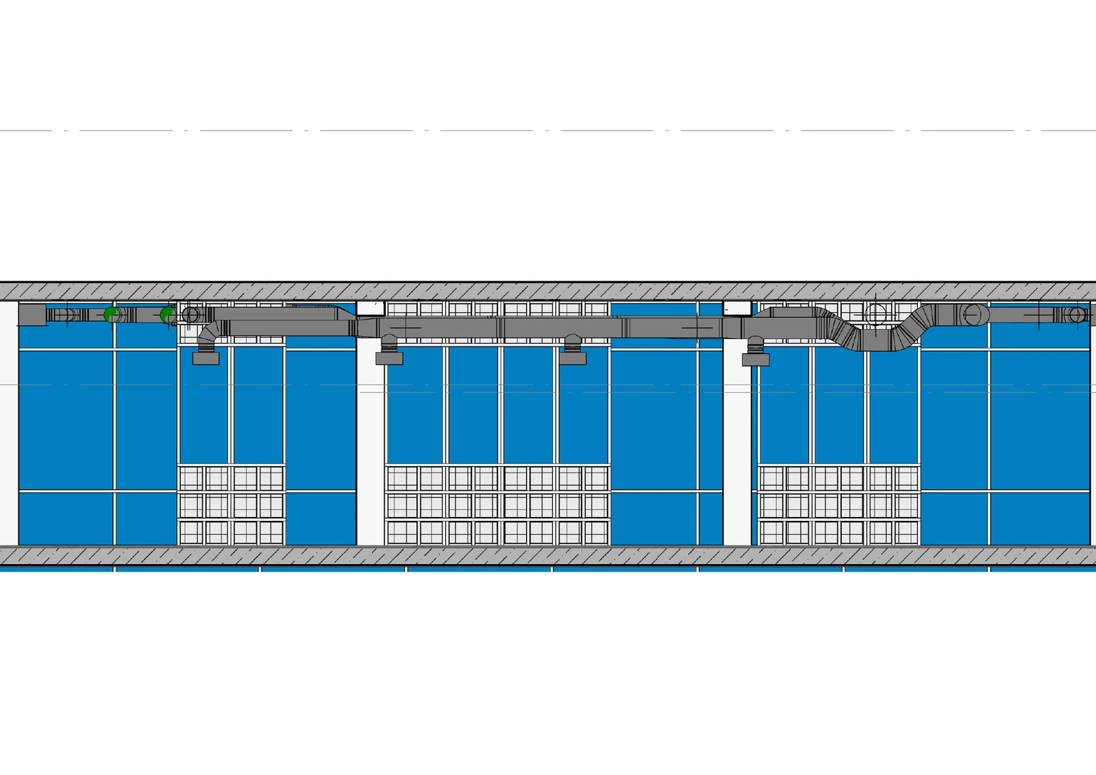
Project example: Restaurant extension and modernisation, approximately 600 m².
Open kitchen: how to limit air transfer into the dining area
During a complete refurbishment of another restaurant, the layout was changed to create an open kitchen. The main task was to coordinate ventilation throughout the space, from the seating area to the cooking area.
Successive transverse supply and extract zones were arranged, each intended to limit unwanted reverse airflow. The key zone was created at the service pass: a directed supply air jet acted as an air curtain and supported airflow towards the kitchen. Active extract hoods operated directly at the emission sources.
This arrangement can be described as staged aerodynamic separation of the open kitchen and dining area. It combines local capture above the cookers, airflow management at the service pass and supply and extract air distribution in the adjoining space. Operating experience showed that the solution achieved its objective with low running costs.
For an open-kitchen owner, this example demonstrates the importance of early coordination between the kitchen consultant, interior designer and engineer. Cooker positions, the kitchen boundary, walkways and the service pass directly affect the eventual arrangement. These should be agreed before ceilings and finishes are fixed.
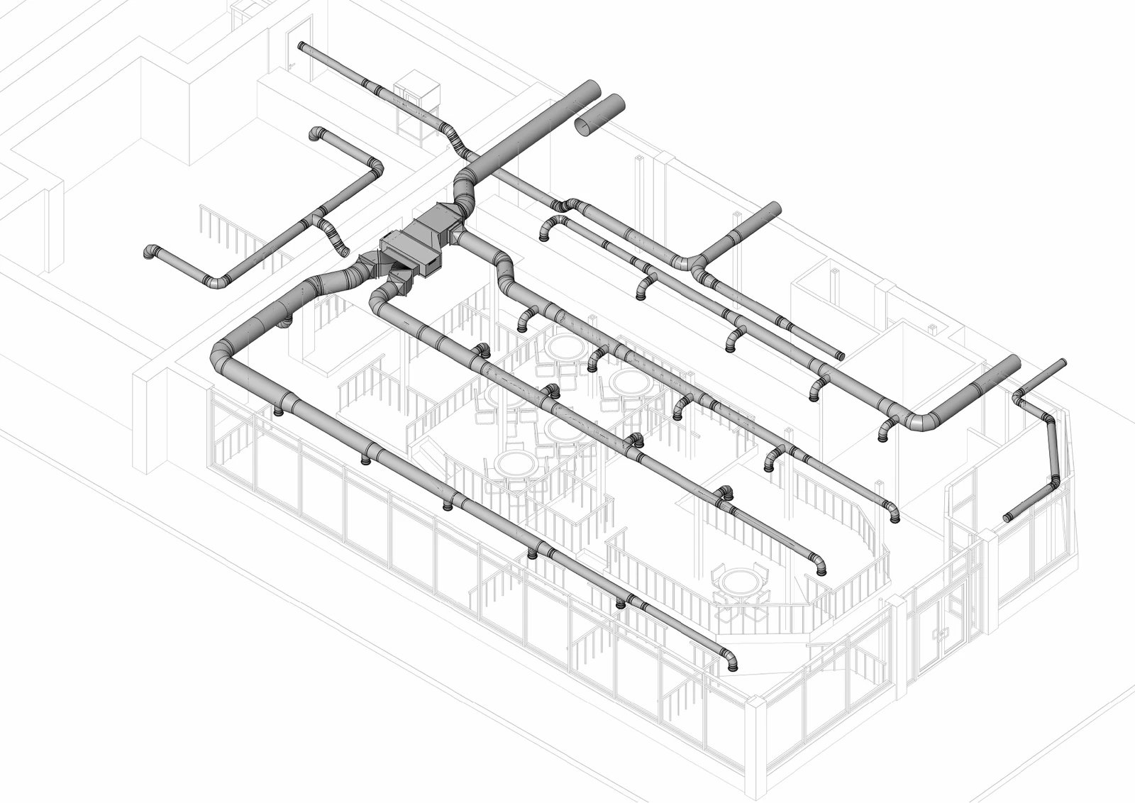
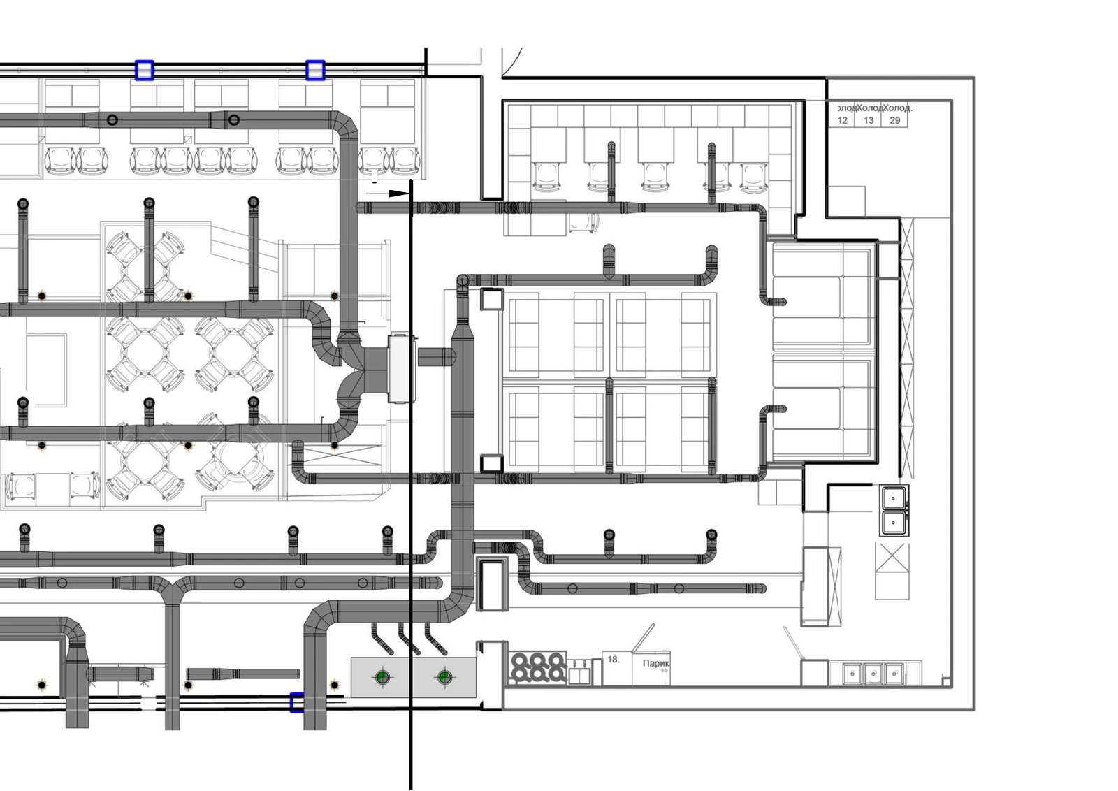
Project example: Restaurant with an open kitchen, approximately 600 m².
Displacement ventilation: attention to the airflow path
In one completed shisha venue project, we used displacement ventilation. Conditioned supply air entered at low level and low velocity, with extract air removed at high level above the sources of contaminants. The target supply air temperature was approximately 2 °C below room temperature; a separate system was installed to condition it.
Experience at the site showed that the chosen air distribution arrangement reduced the required ventilation rate compared with the option initially considered. This avoided the need to increase the connected electrical capacity for winter heating or provide greater air-conditioning capacity to handle a higher outdoor air flow rate.
This example shows how supply and extract locations, temperature and airflow patterns can influence equipment selection. Parameters from one site cannot automatically be applied to another. The description of the ventilation system is not a claim that smoking is safe.
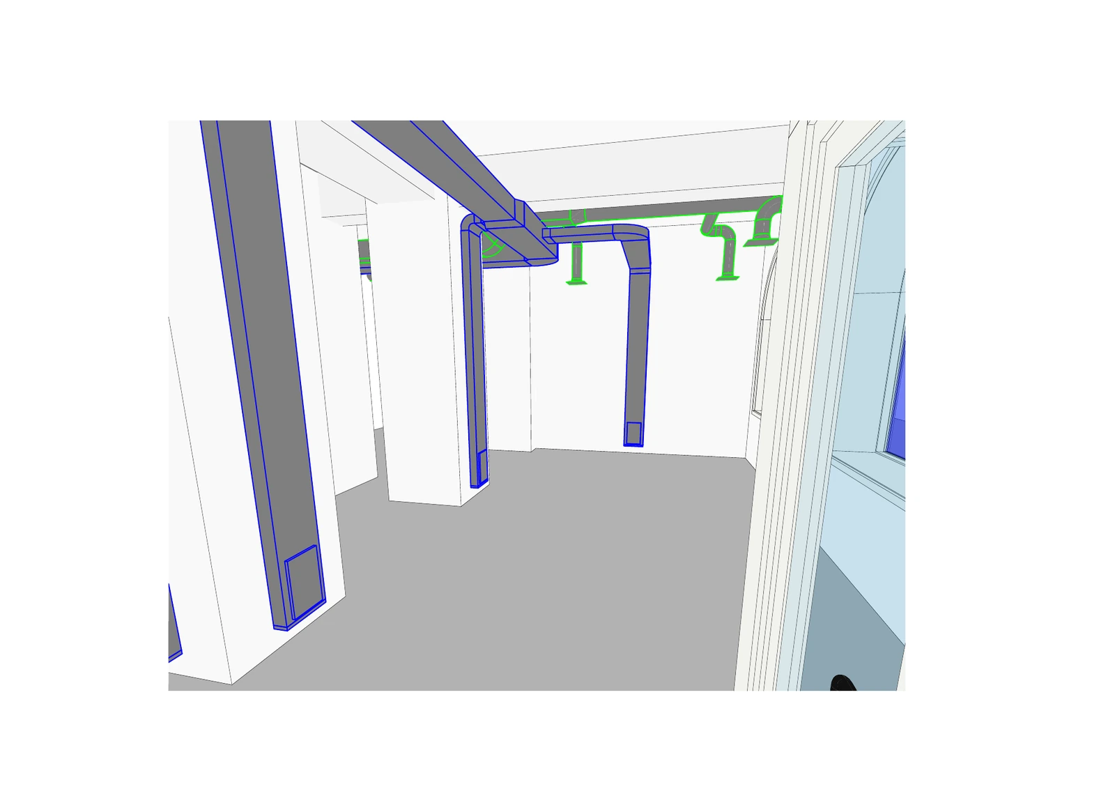
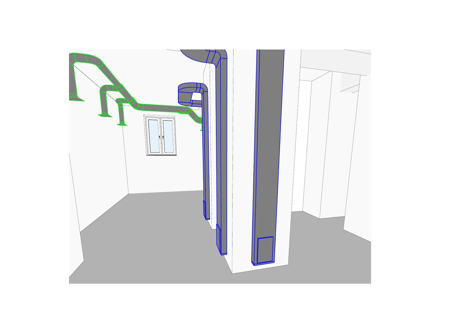
Completed project: Shisha venue with displacement ventilation, approximately 200 m².
Bakery: once-through ventilation with DX heating and cooling
For a small bakery, the production processes and contamination of the extract air led to the choice of a once-through system without heat recovery. Supply and extract ventilation were provided, with outdoor air heated and cooled using Mitsubishi Electric DX equipment.
In the adopted solution, the DX unit heated the supply air in winter and cooled it in summer. Conditioned air was delivered through the ventilation system, integrating central cooling into the air supply to the premises.
Grilles were specifically selected for low air velocities. Displacement principles were also used in part: air was directed gently towards areas of process emissions, limiting unwanted mixing. The combination of air conditioning and air distribution was a distinctive feature of this project.
This example illustrates one option for premises where once-through ventilation has been selected. The feasibility of heat recovery, the heating method and operating modes are determined for the specific production process. For more information on this equipment category, see air conditioning and DX solutions for ventilation.
Completed project: Bakery with DX air conditioning, approximately 150 m².
Restaurant refurbishment: reusing existing systems
Modernisation starts by identifying which parts of the system remain suitable for continued use and the new layout. These may include individual air-conditioning units, ductwork sections or other components. Their suitability is assessed within the proposed system: expansion or changes to the kitchen can alter loads and airflow routes.
On an expansion project, the existing air conditioning was retained and supplemented with new ducted units, while suitable existing ductwork was integrated with new sections. The old ventilation units were removed. Local supply air to the kitchen extract canopies formed part of the solution where electrical capacity was limited.
This approach aligned the restaurant’s new requirements with its existing building services infrastructure. The installation sequence, shutdowns and whether the venue can remain open during refurbishment are determined individually for each site.
For an operating restaurant, a useful starting point is an HVAC technical audit and modernisation. Equipment photographs, the original design and a list of problems are useful for the initial discussion: insufficient supply air, overheating, noise, changes to cooking processes or high costs.
Project example: Restaurant extension and modernisation, approximately 600 m².
Kitchen exhaust discharge: neighbouring windows, residential buildings and air cleaning
Restaurant ventilation must work correctly beyond the venue itself. Once smoke and cooking emissions have been extracted, they must be discharged outdoors without re-entering supply air intakes, reaching neighbours’ windows or causing problems near entrances and outdoor seating areas. The discharge location is therefore determined alongside the extract duct route, before the kitchen layout receives final approval.
Why simply taking a duct to the roof is not enough
The roof of a low-rise restaurant may sit below the windows of a neighbouring residential building. Wind around the taller building creates turbulence and reverse airflow zones. As a result, air from the exhaust stack may not disperse freely: it can return towards the façade or air intakes. Locating the outlet above the restaurant’s own roof does not, by itself, demonstrate that the issue has been resolved. ASHRAE: air intake and exhaust outlet locations.
Design checks cover building heights and relative positions, windows and balconies, supply air intake grilles, possible stack routes, discharge direction and equipment access. If surrounding buildings hinder dispersion, options include relocating the discharge, changing the route or stack height, and air cleaning. The final solution is selected for the specific site and kitchen processes.
A separate requirement applies to premises within or attached to a residential building: clause 7.2.3 of DBN V.2.2-25:2009 requires exhaust discharge above the residential building’s roof and separation of the restaurant’s ventilation from the building’s systems. A filter alone does not remove this requirement. A detached restaurant near residential development requires assessment of its own siting conditions. DBN V.2.2-25:2009, as amended.
What an electrostatic filter can do
Electrostatic air cleaning removes fine smoke particles and grease aerosols from kitchen exhaust air. Inside the unit, particles receive an electrical charge and collect on collector surfaces. This supplements primary grease capture with more thorough cleaning of the extract airflow. How ESP is used in kitchen extraction.
Smoke and odour are not the same thing. Some odours come from gaseous compounds that are not captured with the particles. Where odour control is required, the system may include an additional stage, such as adsorption, selected to suit the composition of the cooking emissions. Manufacturers treat particle removal and odour treatment as separate functions; promising complete odour elimination using an electrostatic filter alone is misleading. Particle removal and odour control: different filter functions.
Practical example: a food court restaurant beside a residential building
At one of our sites, a food court restaurant occupied a two-storey building next to a five-storey residential building. Site constraints prevented the exhaust stack from being raised clear of the adverse effects of the neighbouring buildings.
We used electrostatic filters to clean the kitchen exhaust air. Our team’s operating experience showed that this solution performed well at the site. Regular servicing was essential: at this restaurant, the filters required maintenance every two weeks.
This example demonstrates the practical role of air cleaning in a complex urban setting. It does not mean that installing the same filter permits an exhaust outlet anywhere on a façade. For a new site, the discharge location, impact on neighbours and compliance of the design with applicable requirements must be assessed separately.
Designing for maintenance
An electrostatic filter accumulates contaminants on its working surfaces. Without timely cleaning, its efficiency declines; a running fan does not mean that air cleaning remains adequate. ASHRAE: operational considerations for kitchen electrostatic filters.
Space must be left around the unit for inspection and removal of components. For models with washable cells, provision must be made for cleaning and returning them to service in accordance with the manufacturer’s instructions; consumable components in other stages are replaced according to their maintenance schedules. The service plan specifies who carries out this work and how completion is recorded. Maintaining ESP collector cells.
The two-week interval in this example reflects the experience of one restaurant, not a universal interval for all electrostatic filters. The schedule depends on the equipment, cooking intensity and actual contamination. The feasibility of regular servicing must be considered when selecting the system: cleaning is part of routine restaurant operation, not a one-off task during installation.
Where savings really work
Savings are assessed not by looking at a single unit, but by considering how much air the system actually needs to extract, condition and move in different operating modes.
Extract canopy geometry
Before increasing airflow, check equipment positions, canopy height and overhang, the feasibility of side panels, and the effects of doors, diffusers and other cross-draughts. Effective capture starts with geometry, not an unjustified capacity margin.
Demand-controlled ventilation
DCKV adjusts supply and extract fan output to match the actual kitchen load. Variable-speed control of both airflows must be coordinated, maintain a safe minimum operating level and ensure capture at minimum speed. This type of control is most beneficial where loads vary. The principles are set out in the DOE guide to DCKV.
Transfer air
Some conditioned air from the dining area can be used as make-up air for kitchen extraction, provided this does not compromise conditions in the dining area or the building’s air balance. The transfer airflow rate and route are determined by calculation.
Heat recovery
Heat recovery from dining area extract air is often worthwhile. Grease-laden kitchen extract requires a dedicated arrangement: a conventional plate or rotary heat exchanger is not automatically included in the grease-laden extract path. Contamination, fire safety, cleaning and service access must all be considered.
Electric and induction equipment
This equipment can reduce certain heat and ventilation loads compared with other cooking technologies, but it does not remove the need to extract steam, grease and odours. The effect is assessed for the specific menu and operating pattern.
Recirculating canopies
These are used only as tested, factory-built systems for specified appliances and operating conditions. A recirculating canopy does not remove the need for general room ventilation; the product’s limitations and building requirements must be checked separately. UL explains the broader context of certified systems.
What SM Systems’ work includes
The scope of work is agreed to suit the restaurant’s needs: new construction, review of an existing design, installation or modernisation. For a complete project, we work from the initial information through to on-site system testing.
| Stage | Work carried out | What the client receives |
|---|---|---|
| Initial information and concept | Analyse the layout, kitchen processes, operating patterns and available resources | An agreed system concept and list of initial requirements |
| Design | Determine airflow rates, loads, equipment, routes and service access | Plans, schematics, specifications and requirements for related design disciplines within the agreed scope |
| Procurement and installation | Coordinate supply, positioning and system connections | An installed system in accordance with the agreed documentation |
| Commissioning | Check actual airflow rates, air balance, control modes and equipment operation | Test results and a commissioned system |
| Handover and operation | Hand over the agreed documentation and establish maintenance procedures | A clear equipment schedule and operating requirements |
Learn more: ventilation and air-conditioning design, installation and commissioning.
Testing is needed to assess how the installed system performs under the venue’s actual operating conditions. Air balancing and recording the results are important parts of commercial kitchen commissioning, as also emphasised in the ASHRAE Handbook, Kitchen Ventilation chapter.
What is checked during commissioning
Commissioning confirms not just that the fans start, but that the system works under actual kitchen and dining area operating conditions.
- actual airflow rates at each extract canopy, the kitchen supply and the dining area ventilation;
- airflow direction between zones;
- capture of smoke and steam while equipment is operating;
- operation under simultaneous loads and the effect of opening doors;
- temperature in the kitchen working zone;
- noise and vibration;
- variable-speed control operation and coordination of supply and extract airflows;
- the interlock that shuts down kitchen equipment on extract failure, where specified in the design;
- fault signals, water scrubber and pump operation;
- the fire response sequence and shutdown mode for solid-fuel equipment;
- absence of exhaust air re-entry at air intakes, windows and entrances.
What is handed over to the client
- as-built documentation and measurement results;
- control sequences and an equipment schedule;
- instructions and a maintenance schedule;
- a list of consumables;
- contact details for the responsible service providers, where included in the contract.
Maintenance considered at the design stage
Experience with projects featuring water scrubbers and an integrated wood-fired oven has demonstrated the importance of equipment access. It must be clear from the outset how staff or the service team will open the assembly, clean it and inspect the pump. The layout must retain the necessary access routes and working space.
For a restaurant with several functional areas, system operating modes must also be clearly organised. The preparation kitchen and dining area may start operating at different times. Controls are considered alongside kitchen processes and the ventilation balance; the control system specification is determined by the design. For more on this area, see automation and BMS.
Maintenance intervals are not determined by the calendar alone. They depend on cooking methods, operating hours, grease and smoke volumes, fuel type, actual contamination, manufacturer requirements and the condition of filters, ductwork and fans.
The log records inspections, cleaning, filter replacements, faults, control system activations and changes to kitchen processes. After kitchen equipment or menu changes, the adequacy of extraction must be checked again.
For kitchen extract systems, the service plan separately specifies cleaning of the grease-laden extract path, water scrubber checks and maintenance of electrostatic components, where fitted. Fire suppression inspection procedures are agreed with the system installer and aligned with its documentation. The fortnightly servicing of electrostatic filters at the food court restaurant described above reflects that particular site’s experience, not a universal interval.
Diagnosing problems in an existing system
A single symptom can have several causes, so a remote description cannot replace measurements and a system inspection.
| Symptom | What to check first |
|---|---|
| Odours reach the dining area | Canopy capture, kitchen and dining area air balance, transfer airflow direction and extract operation |
| Smoke escapes from under the canopy | Equipment position, canopy geometry, airflow rate, cross-draughts and duct contamination |
| The kitchen is too hot | Make-up air supply, its temperature and distribution, actual heat gains and air-conditioning operation |
| Doors are difficult to open | Excessive negative pressure, supply and extract airflow rates, transfer openings and operating modes of other systems |
| Draughts at workstations | Supply air velocity and direction, diffuser locations and make-up air provision near the canopy |
| Neighbours complain about odours | Discharge location and direction, air-cleaning system condition, neighbouring building heights and actual kitchen processes |
| Grease appears outside the canopy | Capture, filters, equipment position, cooking practices and system cleaning |
| The fan is running, but performance has deteriorated | Filters, duct deposits, belts and impeller, dampers and actual airflow rate |
| Energy consumption has risen sharply | Control modes, fouling, temperature setpoints, simultaneous operation and heat exchanger condition |
| The system has become noisier | Vibration isolation, fixings, bearings, fan fouling, air velocity and silencers |
What determines the cost of restaurant ventilation
Floor area provides only an initial picture of the premises. A quotation requires details of the cooking equipment line-up, fuel type, hood sizes and positions, dining area layout, cooling requirements and supply air heating method. Duct routes, the extract discharge point, equipment space and noise restrictions also matter.
For refurbishment projects, the condition of existing systems must also be considered. Retaining serviceable components may change the scope of work, but their suitability for the new loads must first be assessed. Available electrical capacity is another factor: it was a significant constraint in several of the examples presented.
After reviewing the initial information, an engineering concept and an agreed scope for the proposal are developed. The proposal should clearly define the equipment, installation work, commissioning and subsequent servicing terms.
Cost is determined by more than floor area and equipment prices. The scope may include design, duct routes, shafts and roof penetrations, steelwork, fire protection, noise attenuation, water supply and sewerage, electrical supply, controls, air cleaning equipment, commissioning, measurements, maintenance access, equipment lifting and removal of existing systems. For an operating restaurant, the feasibility of carrying out work without a complete shutdown is assessed separately.
A universal price per square metre does not reflect these differences or allow the completeness of solutions to be compared.
How to compare contractors' proposals
Commercial proposals should be compared using the same design inputs and boundaries of responsibility. Each proposal should specify:
- design airflow rates and the list of equipment used in the calculations;
- outdoor air conditions, heating and cooling capacities, and the heat source;
- required electrical capacity;
- the provision for grease, smoke and odour removal;
- the method of providing make-up air;
- noise attenuation and vibration isolation;
- fire protection, fire suppression and boundaries of responsibility;
- controls, fault alarms and operating mode descriptions;
- structural openings, penetrations, water supply, sewerage, drainage and electrical power;
- installation, commissioning, measurements and capture testing;
- as-built documentation, warranty, servicing and consumables.
Compare the complete system, boundaries of responsibility and acceptance criteria, rather than simply a list of units.
Approaches that are generally unsuitable
- extract ventilation with an unjustified capacity margin;
- an air conditioner used to compensate for untreated supply air;
- a standard heat recovery unit in a grease-laden extract path without a purpose-designed solution;
- an electrostatic filter treated as permission to discharge air anywhere;
- a wet scrubber without verified functionality and a specified permissible temperature;
- controls without defined operating modes;
- equipment without cleaning access;
- a fan without actual measurements after installation.
Fire safety for a wood-fired grill: dedicated extract, protected ductwork and maintenance
Extract air from a wood-fired grill contains hot combustion products, sparks and cooking contaminants. Deposits inside the system can sustain combustion. Protection must therefore cover the entire airflow path: from the fire and hood through the cleaning equipment and fan to the discharge point. Below, we examine the principles of system selection and operation.
A dedicated system for the grill
An open wood-fired grill requires a dedicated extract path: its own hood, ductwork, necessary cleaning stages and extract equipment. It must not be connected to the general ventilation serving the dining area, toilets or residential part of the building. Combining it with hoods over other cooking equipment is not treated as a standard solution either.
Ukraine’s DBN V.2.2-25:2009, clause 7.2.5 requires local extract systems to be separated from general extract ventilation. Specialist guidance for solid-fuel kitchens also calls for a separate extract route from the grill, as illustrated in Halton’s guidance on ventilation for solid-fuel equipment. International guidance is applied with regard to Ukrainian regulations and the selected system’s documentation.
A short, straightforward route with minimal bends
The extract route should be agreed before the layout and finishes are finalised. The aim is to avoid unnecessary bends, restrictions, dead-end branches and details where deposits could accumulate. Every necessary bend must remain accessible for inspection and cleaning. A complex diversion around structural elements must not become a concealed section that cannot be reached after installation.
Minimising obstructions does not mean omitting necessary grease capture, spark arresting or air cleaning. These devices are included in the design as functional system components, with access and space for maintenance. Locating a wet scrubber near the hood must take account of temperature limits, equipment design and service access.
Why standard slide dampers and fire dampers are unsuitable here
Standard regulating slide dampers, non-return dampers or fire dampers intended for general ventilation are not specified in the grease-laden extract path from a grill. They create grease accumulation points, hinder cleaning and may block the removal of combustion products while the fuel is still burning. A standard damper must not be used as a universal means of protecting a floor penetration by this type of duct.
However, an absolute statement that ‘all dampers are prohibited’ would be inaccurate. Specifically tested devices are available as part of factory-made systems for the relevant application. For example, the manufacturer of Halton KVE-CM lists such an option for its specialist hood. This does not permit the installation of an arbitrary damper: use of a specific device must be provided for in the design, manufacturer’s documentation and system requirements.
Leak-tight metal ductwork and a suitable fire-protective enclosure
Ductwork is selected for a hot, grease-laden airflow. Important considerations include leak-tight joints, materials suitable for the temperature and cleaning methods, allowance for thermal movement, and safe collection and removal of deposits. The construction must prevent grease leaking onto building structures. Factory-made grease duct systems have specific requirements for joints, supports and access components; DuraVent DuraStack Pro Grease Duct is an example of such documentation.
In terms of the attention required to heating of surrounding structures, this extract path does resemble a flue. However, a standard twin-wall fireplace flue or non-combustible insulation cannot automatically be considered suitable protection for a restaurant grease duct. Thermal insulation limits heat transfer; the required fire resistance is provided by an appropriate tested construction — a protected duct, enclosure or shaft specified in the design. Manufacturers explicitly distinguish arbitrary wrapping from protection tested specifically for grease ducts.
Wall and floor penetrations, interfaces with combustible materials, fixings and access hatches require separate consideration. Omitting a standard fire damper does not remove the need to maintain the fire resistance of the separating element. A complete engineered solution is required, not merely insulation around the visible section of ductwork.
Spark arresting and wet scrubbers
The suitability of a wet scrubber or other device for the sparks and temperatures produced by a particular grill must be checked against the manufacturer’s documentation. The term ‘wet scrubber’ alone does not define its permitted applications. If spark arresting is required, it must be clear which component provides this function and under what operating conditions. Not every grease filter should automatically be regarded as a spark arrestor.
Water-based cleaning requires advance provision for water supply, removal of contaminated effluent, cleaning of working components, pump monitoring and service access. It must be established how staff will be alerted to a fault and what they should do until operation is restored. The need for redundancy is assessed for the specific arrangement; a standby pump does not replace operational monitoring and maintenance.
Fire suppression is considered separately from air cleaning
A wet scrubber should not be equated with an automatic fire suppression system. The kitchen requires defined protection zones, fire detection and suppression methods, manual activation, equipment interlocks and inspection procedures. Protection is selected specifically for the type of fire source and cooking process. System manufacturers such as ANSUL describe protection of cooking equipment, the hood and extract path as a coordinated system; suitability for a particular wood-fired grill must be checked separately.
Ukraine has an explicit requirement to consider: clause 9.14 of DBN V.2.2-25:2009 calls for automatic or autonomous fire-suppression systems for the kitchen ventilation systems, exhaust ducts and enclosures specified in that clause at establishments with 50 or more seats where cooking with gas, wood, charcoal or open flames may involve burning grease. The clause refers to DBN V.2.5-56. Fewer seats do not automatically remove other requirements: the building, equipment and all applicable documents must be assessed.
Operation after cooking and fault response
Wood and charcoal do not stop burning when electrical power is switched off. Closing the kitchen must therefore not automatically shut down extraction above fuel that is still hot. Operating procedures must define the operating mode until combustion has fully ceased and safe cooling has been achieved, as well as actions following loss of extraction, water or power. The British government agency HSE, in its guidance for solid-fuel kitchens, specifically addresses ventilation, carbon monoxide and operation after cooking has finished. This is useful technical guidance, not Ukrainian legislation.
Normal operation and the fire response sequence are different scenarios. Commands to the fan, supply air system, alarms and fire suppression system must be coordinated in the design; a universal rule to ‘switch everything off in any emergency’ is unsuitable for solid-fuel appliances. Carbon monoxide monitoring is considered an additional measure, not a substitute for properly functioning ventilation.
Cleaning, fuel, ash and staff responsibilities
Inspections cover not only the hood and wet scrubber but also accessible duct sections, bends, access points and the fan. Inspection and cleaning intervals are set according to instructions, workload and actual deposit accumulation. Completed work and identified faults are recorded in a log. Procedures are reviewed after cooking equipment is replaced or operating patterns change.
Fuel is stored in a designated location, away from hot surfaces and escape routes; ash and charcoal residues are removed into suitable non-combustible containers. Staff must know who monitors the system, how to report a fault and how to respond to a fire. A standard water jet must not be directed at burning grease. Heartland Fire & Rescue also treats dedicated extraction, cleaning, fuel and ash handling, and staff training as an integrated set of measures.
Frequently asked questions
Let’s discuss an engineering solution for your restaurant
Send a plan of the premises and a brief description of the task: a new opening, an open kitchen, a wood-fired grill, expansion or upgrading existing systems. Include photographs and design documentation if available. SM Systems will help define the ventilation and air conditioning requirements, initial constraints and the next step towards implementation.
Prepared by Yaroslav Smolko, SM Systems.