
SOLUTIONS FOR PRIVATE HOMES
Building services for flats, houses and apartments
How to coordinate ventilation, heating, cooling, humidity, hot water and controls with the architecture and your lifestyle — without noise, draughts, unnecessary equipment or costly alterations.
Comfort in a private home does not come from a single air conditioner, boiler or heat recovery unit. It emerges when the building envelope, ventilation, heating, cooling, humidity control, controls and architecture work as one system.
A flat, a house and a private apartment may have the same floor area yet require fundamentally different solutions because of the façade, shared building systems, available space, lifestyle and maintenance access.
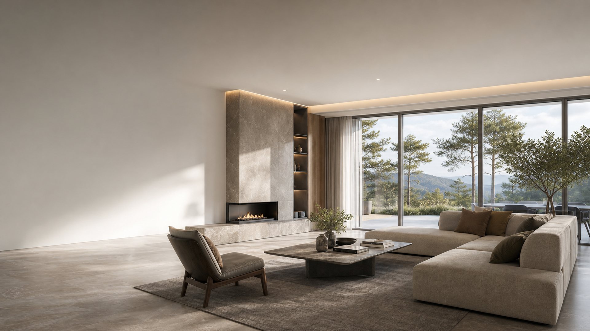
The same need for comfort — different engineering possibilities
| Format | Characteristics | What is usually possible | Main constraints |
|---|---|---|---|
| Flat | Shared shafts, façade and building systems | Local air conditioning, compact ventilation, integration with central heating | Façade, ceiling height, noise affecting neighbours, central extract ventilation |
| Penthouse | Extensive glazing, roof, terraces, complex zones | Central ventilation, ducted systems, individual heating where conditions allow | Solar loads, service routes, wind, rooftop equipment |
| New-build house | Systems can be planned before construction | Central ventilation, heat pump, surface heating, full automation | Early coordination and plant rooms |
| Existing house | Completed architecture and finishes | Phased upgrades, local or combined solutions | Limited service routes, existing electrical and heating systems |
| Townhouse | Your own section of the building, but neighbours close by | Individual systems and zonal control | Noise, outdoor units, shared architecture and limited plot size |
| Seasonal home | Long periods of absence | Protective operating modes, remote monitoring, preparation before arrival | Freezing, lack of monitoring, unreliable power supply |
| Private apartments | High standards for interior design and comfort | Concealed ducted systems, individual zones, automation | Shared building systems and restricted maintenance access |
Floor area is only one of the design inputs. Building type, façade, shared systems, service routing options and equipment maintenance access are often more important. A flat and a house of the same size may have fundamentally different systems.
Private apartments used as permanent homes fall within the residential scope of this page. For serviced apartments operated as hotel accommodation, see our Hotels and Aparthotels solution.
Design starts with lifestyle, not a list of equipment
Before selecting equipment, we establish who uses the home and when. The number of residents, children, guests, pets, working from home, night-time schedules, extended trips and different temperature preferences determine the actual load. Filtration requirements can be raised for allergy sufferers without making medical promises about the building services system.
People and schedules
- permanent or seasonal occupancy;
- bedrooms, children's rooms, home office and guest rooms;
- preparing the home before arrival;
- individual temperature settings.
Architecture
- façade orientation and glazed area;
- double-height spaces, terraces, basement and roof;
- ceiling heights, shafts and outdoor unit locations;
- maintenance access routes and plant rooms.
Resources
- allocated electrical capacity and gas supply;
- water, central heating and drainage;
- generator, battery storage or solar power system;
- scope for a backup heat source.
Expected outcome
- temperature, humidity and air quality;
- night-time noise level;
- degree of equipment concealment;
- control scenarios and operating budget.
Any swimming pool, spa, home cinema, wine room, conservatory, workshop, garage, server room or communications cabinet is listed separately. This information forms the brief for HVAC design, translating requirements into design operating conditions.
HVAC should not compensate for building defects
Thermal loads are not determined by floor area alone. Important factors include glazing orientation and size, solar shading, the thermal conductivity of the building envelope, thermal bridges, airtightness, infiltration, the roof, the ground floor and actual internal heat gains. A panoramic window facing south-west can create a higher summer peak load than several north-facing rooms.
If the façade overheats, external solar shading and glazing are assessed before increasing cooling capacity. If the building envelope has cold surfaces or air leaks, more powerful heating will not eliminate local discomfort or condensation risk. For a new house, the building envelope, heat losses and heat gains are assessed together.
For refurbishment, a thermal imaging survey in the appropriate season, airtightness testing and analysis of actual energy bills are useful. They help distinguish equipment problems from building envelope problems. Design calculations are still necessary: a single cold or hot day does not reveal the building's full behaviour, and energy use also depends on residents' habits.
Building services maintain design conditions. They should not be an expensive way to conceal shortcomings in the façade, insulation or airtightness.
Comfort is about more than air temperature
Two rooms at the same 22 °C can feel different. People are affected by surface temperatures, solar radiation, air velocity, vertical temperature differences, humidity, clothing and activity. That is why a strong jet from an air conditioner does not always provide comfort, and underfloor heating does not always offset the cold from large areas of glazing.
Criteria are set for each zone: the acceptable temperature range, air direction and velocity, night-time noise, humidity and time to reach operating conditions. In bedrooms, quiet operation and freedom from direct draughts take priority; in a study, ventilation and local control matter; and in a double-height living room, stratification must be considered.
Air quality starts with controlling pollution sources
Ventilation dilutes pollutants, but does not remove the need to control their source. Finishes, furniture, household chemicals, cooking, candles, printers, damp building elements and the garage can affect air quality more than the number of occupants. Airing the home and controlling humidity after finishing work are useful before moving in.
CO₂ is a useful indicator of occupancy and ventilation adequacy in bedrooms or a study. It does not indicate all volatile compounds, dust, odours or combustion products. Fine particulate and VOC sensors can be useful for tracking trends, but their readings must be interpreted alongside how the home is being used, rather than treated as definitive laboratory measurements.
For homes with a basement or ground contact, the risk of radon is assessed separately. The garage and boiler room are separated from living areas through air balancing and airtight construction.
An open window helps, but does not replace a system
Opening windows is useful as a supplementary measure, but depends on wind, temperature, noise, dust, security and occupant behaviour. At night or when the home is unoccupied, it does not guarantee the required air change rate. In winter it creates local cold draughts, while in summer it can bring in humid air and increase the cooling load.
Controlled ventilation supplies filtered air to bedrooms, children's rooms, the study and living room, moves it through the home and extracts it from the kitchen, bathrooms and dressing rooms. Heat recovery recovers some of the heat, but does not cool the home like an air conditioner and is not a stand-alone dehumidifier.
In a flat, the whole building must be considered
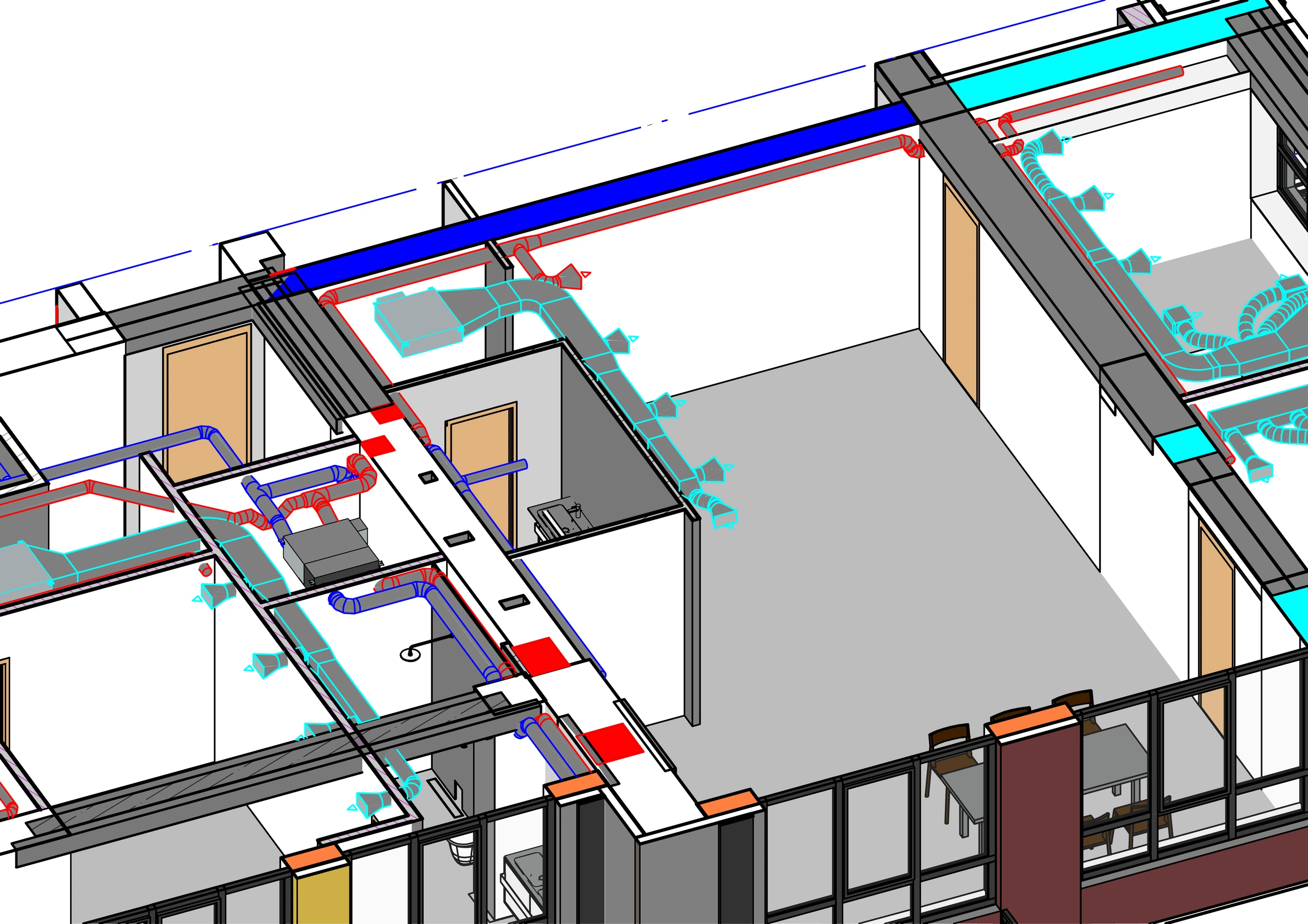
In a flat, the first step is to inspect shared shafts, existing air supply, draught direction, extract performance on different floors and façade rules. Connecting a fan to a natural ventilation shaft without checking it can transfer odours to neighbours or obstruct extraction under other operating conditions. New airtight doors and windows also alter the original balance.
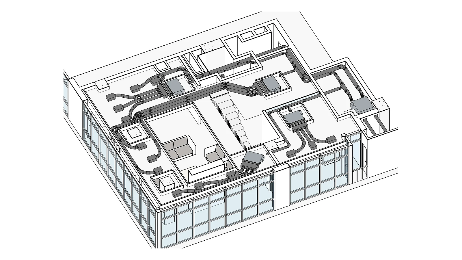
A central supply and extract air handling unit provides control over filtration, heat recovery and air balance, but requires space and ductwork. A compact supply air system using existing extract shafts may be possible following measurements. Decentralised units remain an option for finished interiors, provided façade openings, local noise and multiple service points are acceptable.
A detached house offers more freedom, but requires full coordination
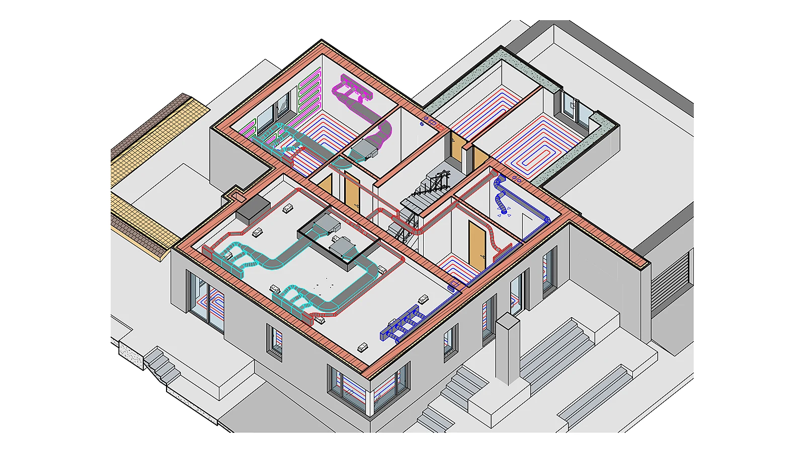
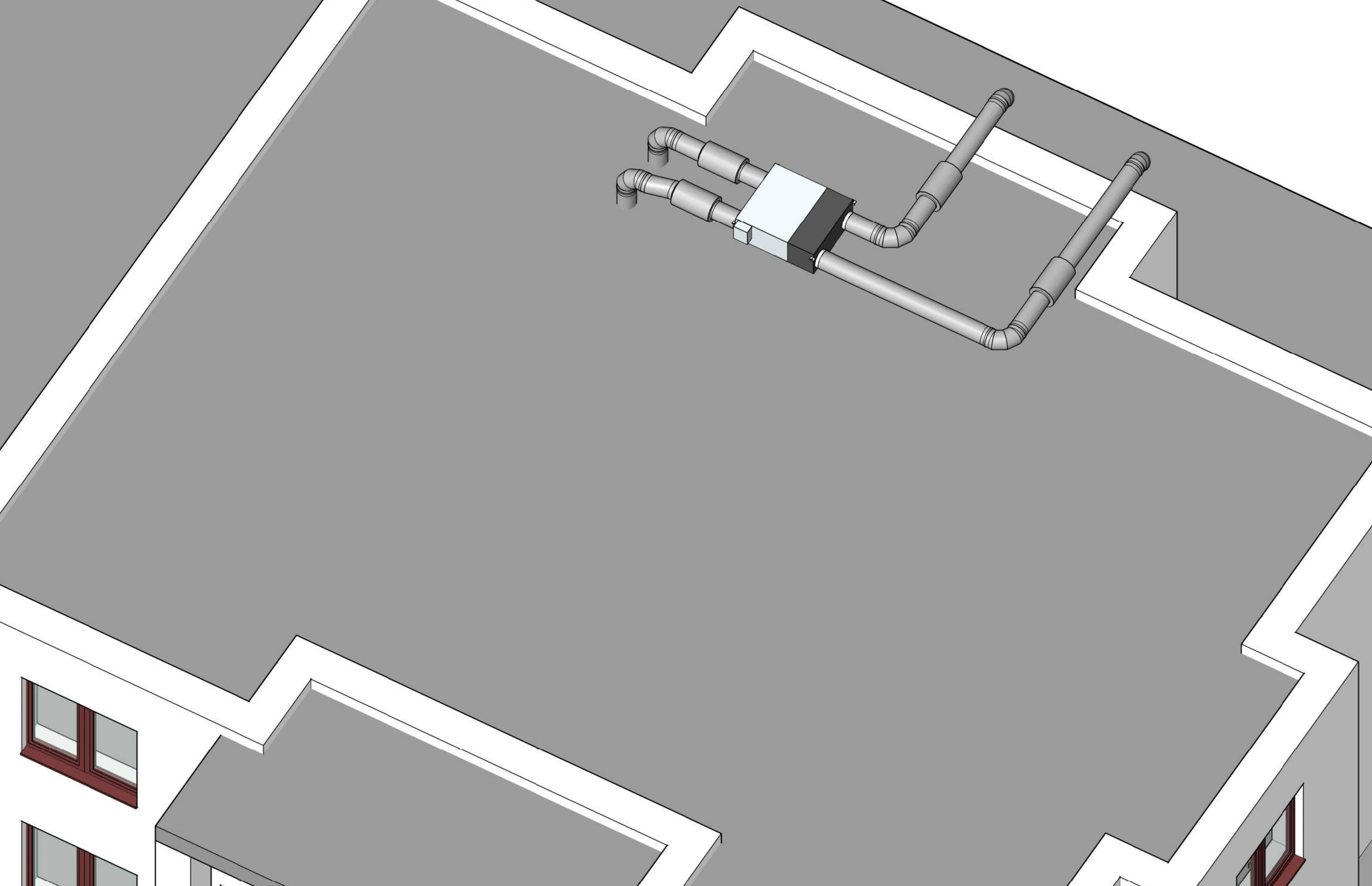
In a detached house, central ventilation, low-temperature heating, a heat pump, zoned cooling and controls can be designed as a single system. This freedom only works with early planning: space is needed for a plant room, shafts, air intakes and discharge points, outdoor units, drainage, electrical supplies and routes for removing equipment for servicing.
Air balancing covers living rooms, bathrooms, the kitchen, dressing rooms, boiler room, garage and basement. Air must not be drawn into the home from the garage or plant areas. For a seasonal residence, frost protection, leak detection, remote notifications and system preparation before arrival are also included.
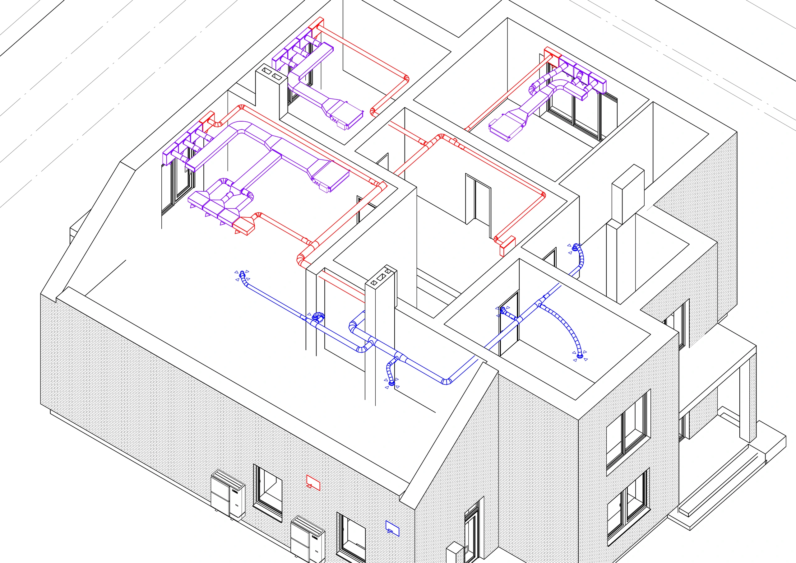
Filters must be selected to suit the fan and outdoor conditions
A higher filtration class increases resistance and the demands on the fan. Simply fitting a denser filter to a system without spare pressure capacity will reduce airflow, increase noise and leave occupants with poorer ventilation. The design accounts for initial and final resistance, filter area, replacement access and a dirty-filter alert.
In urban areas, fine particulates and the air intake location matter. Near a road, car park, exhaust outlet or generator, even a good filter cannot compensate for a poorly located grille. An activated carbon stage can reduce some odours and gaseous pollutants, but has a limited service life and does not replace proper separation of air streams.
The heat source and heat delivery method are separate decisions
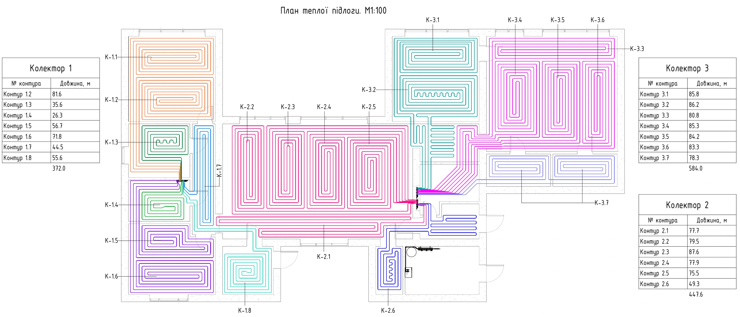
A boiler, heat pump or central heating substation provides heat. Floors, walls, ceilings, radiators, convectors or an air heating system deliver it to the room. These must be matched in terms of flow and return temperatures, thermal inertia, architecture and peak heat losses.
| Solutions | Suitable applications | Strengths | What to check |
|---|---|---|---|
| Gas or electric boiler | Homes with an available energy supply and a wet heating system | Straightforward hydraulics, rapid temperature recovery | Incoming supply capacity, flue arrangements, tariff, backup and safety |
| Air-to-water heat pump | Energy-efficient homes with low-temperature heating | One source for heating, cooling and hot water | Output in freezing conditions, defrosting, noise, backup and flow temperature |
| Hybrid system | Properties with different tariffs or backup requirements | Source selection to suit conditions and reduced failure risk | Source priority logic, hydraulics, controls and servicing |
| Communal building heating | Flats and apartments in a multi-residential building | No individual heat source | Available flow and return temperatures, balancing, metering and limits on alterations |
| Heat delivery | Comfort and response | Constraints |
|---|---|---|
| Underfloor heating | Even low-temperature heat, high thermal inertia | Floor finish, pipe spacing, surface temperature and slow response |
| Wall or ceiling heating | Gentle radiant heat, useful near glazing | Coordination with furniture, fixings, lighting and finishes |
| Radiators and convectors | Faster response and local compensation for cold surfaces | Flow and return temperatures, convection, positioning within the interior |
| Air heating | Rapid temperature changes through a ducted system | Air movement, noise, stratification, high airflows and large duct cross-sections |
For panoramic glazing, the internal surface temperature and cold downdraught are checked. A convector near the façade, wall heating or another local solution may be more important than raising the temperature of the entire floor. Zoned control must not conflict with the heat source's minimum flow requirement or the system hydraulics.
Choose a heat pump to suit the system, not its rated COP
The rated COP describes performance at specific temperature conditions. For an actual home, checks cover heating output at the design outdoor temperature, flow temperature, defrost cycles, part-load operation, hot water production, noise and available electrical capacity. High-temperature radiators can significantly affect efficiency.
Backup is determined by the consequences of failure, not by a rule of adding another identical unit. A well-insulated home with high thermal inertia can maintain a safe temperature for a time, whereas an unattended seasonal residence needs a separate protection strategy. Read more about heat pumps and compatibility with a radiator system.
Cooling must be designed room by room
An overall capacity based on floor area does not show where and when loads occur. An open-plan kitchen and living room with panoramic glazing, an east-facing bedroom, a study with equipment and a loft room have different peaks. Room-by-room calculations determine the number of zones, airflows and supply air locations.
| Solutions | Advantages | Key risks |
|---|---|---|
| Wall-mounted split systems | Simple zoning, accessible servicing, phased installation | Indoor units in the interior, air jets, façade and outdoor units |
| Ducted air conditioners | Concealed integration and flexible air distribution | Ceiling void space, noise, drainage, access and duct balancing |
| Multi-split or VRF | Multiple zones on a shared outdoor circuit | Pipe run lengths, minimum loads, refrigerant charge and backup |
| Fan coil units | Water-based distribution, various cooling sources | Hydraulics, condensate, fan noise and servicing |
| Surface cooling | Minimal air movement and highly unobtrusive integration | Dew point, limited capacity, thermal inertia and the need for dehumidification |
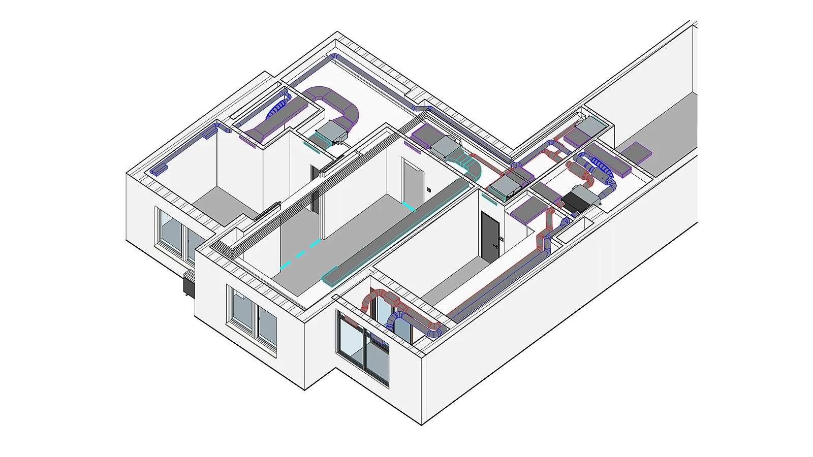
Air distribution is checked against the furniture layout. Air jets must not be directed at beds, sofas or workstations. For a ducted system, return air, transfer air between rooms, noise attenuation, drainage and inspection access are important. The equipment's minimum output is checked separately to prevent short cycling in spring and autumn.
A room with a door needs a return air path to the indoor unit: a separate grille, duct or sized transfer opening. Otherwise, closing the door changes airflow and pressure. Where several rooms share one ducted unit, damper control is checked in every combination to ensure that closing one zone does not cause noise or excessive airflow in another.
Humidity must be controlled alongside building surface temperatures
Relative humidity depends on temperature. Winter dryness can result from excessive ventilation, air leakage and very warm air, not just the absence of a humidifier. In summer, cooling without sufficient moisture removal can deliver an acceptable temperature but leave a clammy feeling and a risk of condensation.
Humidification is designed with water treatment, hygienic maintenance, drainage and limits based on the temperatures of windows and external corners. Dehumidification for a pool, spa, basement or seasonal home is calculated from moisture loads. An enthalpy heat exchanger can recover some moisture; its benefits and limitations are covered in the article on enthalpy heat recovery.
Control based on a single corridor sensor often fails to reflect conditions in a bedroom, bathroom or basement. Measurement points are selected according to risk and checked with a reference instrument. Controls should respond to the duration and magnitude of a deviation, rather than a single spike after a shower, to avoid unnecessary noise and over-drying other zones.
A cooker hood changes the air balance of the whole home
A cooker hood must capture pollutants at source and discharge them via a permitted route. Its performance depends on the canopy shape, mounting height, hob type, duct length and resistance. A very high catalogue airflow figure does not guarantee results once connected.
Every cubic metre of extracted air must be replaced. In a flat, the shaft capacity and building rules are checked; in a detached house, a boosted supply air mode is included. This is particularly important where there is a fireplace, gas equipment or a door to the garage. A filtered recirculating cooker hood reduces some aerosols and odours, but does not discharge moisture or combustion products outdoors.
Moisture and odours must be extracted at source
Bathrooms, the utility room, dressing rooms and plant rooms need extraction and a make-up air path. A humidity sensor or boost button is only useful when the base operating mode is already balanced. After a shower, the system should remove moisture without hours of noise.
In the utility room, the tumble dryer, heat gains and lint are taken into account. Dressing room ventilation must not carry odours from the bathroom. Basements and cool storage rooms are checked against surface temperatures: excessive airing with humid summer air can sometimes increase, rather than reduce, condensation risk.
Hot water is about delivery capacity, waiting time and safety
The hot water system is sized according to the number of bathrooms, simultaneous shower use, baths, the kitchen, occupants' habits, storage volume and recovery rate. A large cylinder does not compensate for insufficient heat source capacity, and a powerful heater does not eliminate long waits at distant outlets.
Hot water circulation reduces waiting times but continually loses heat through the pipes. The pipework is insulated and circulation is controlled by schedule, temperature or occupancy, without creating hazardous stagnant sections. For a heat pump, the assessment covers domestic hot water priority, storage temperature, hygiene cycles, backup heating and the effect on space heating during peak demand.
Quiet operation is designed in before installation
Noise comes from fans, compressors, valves, high air velocities in ducts and grilles, turbulence, structural vibration and sound transfer between rooms. The catalogue noise level of a single unit does not describe the sound in a bedroom after installation.
A night-time noise criterion is set for the design, equipment is located away from noise-sensitive rooms, flexible connectors, anti-vibration mounts and attenuators are used, velocities are kept within limits and valve settings are checked. Outdoor unit noise is also assessed at neighbouring windows and the site boundary. After commissioning, noise is measured in typical operating modes, not just at minimum speed.
A concealed system must still remain accessible
Interior design can conceal grilles, ducts and equipment, but not eliminate servicing needs. An access hatch must allow filters to be replaced, drains cleaned, valves checked, fans removed or a unit dismantled. A small decorative opening beneath the equipment is not adequate access.
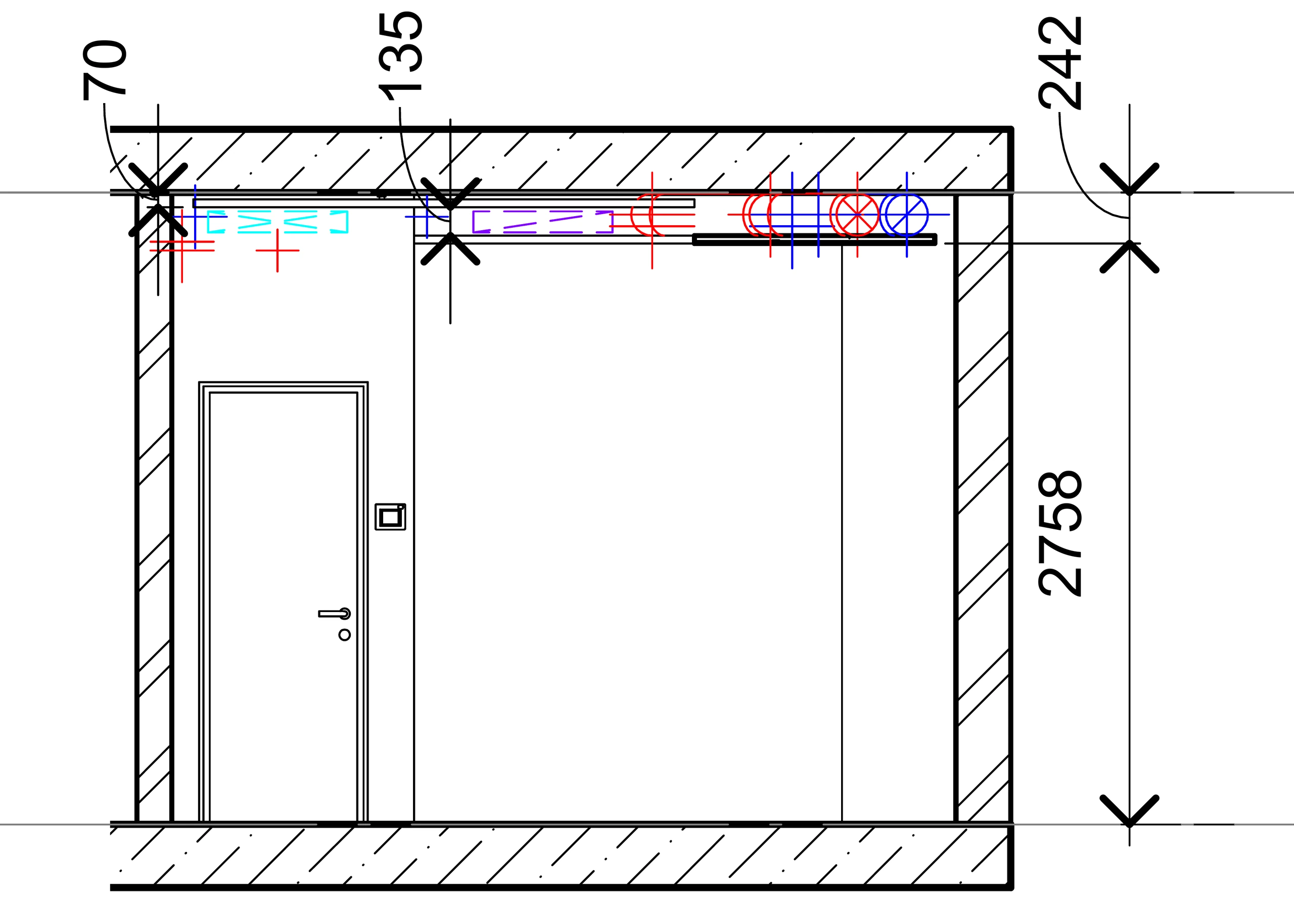
The coordination model is used to check ceilings, light fittings, cornices, furniture, electrical services, sprinklers and duct routes. Diffusers are selected together with airflow, air jet geometry and junction details. Before ceilings are closed, routes are photographed, equipment is labelled and as-built drawings are prepared.
Every specialist room has its own indoor climate requirements
Pool and spa
Dehumidification, air supply to cold enclosing surfaces, corrosion-resistant materials and a separate operating mode when the water is covered.
Home cinema
High heat gains, quiet ventilation, prevention of sound transfer and equipment room cooling.
Wine room
Stable temperature and humidity, a vapour barrier, condensation control and independent controls.
Conservatory
Solar gains, moisture, irrigation, shading and operating conditions kept separate from living areas.
Garage and workshop
Pollutant extraction at source, pressure separation and prevention of air transfer into the home.
Server room or communications cabinet
Year-round heat gains, independent cooling, alarms and operation while occupants are away.
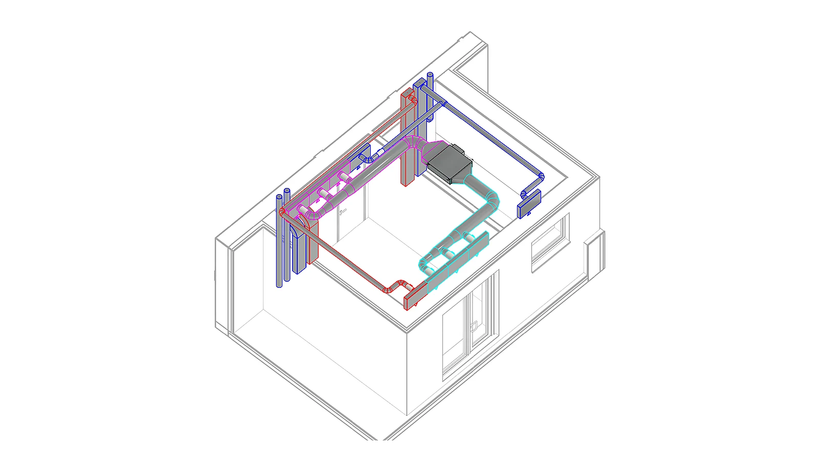
A smart home should make everyday use simpler
Users need clear modes: home, night, away, guests, intensive cooking, holiday and emergency. The controls coordinate ventilation, heating, cooling and humidity without requiring residents to adjust each valve separately.
Local equipment protection remains autonomous. The central system sets operating modes, records trends and indicates dirty filters, leaks, pump failures or parameters outside their limits. Remote access must include user roles, backups and the option of manual control without a cloud service. Read more about HVAC automation and the HVAC Intelligence approach.
Weather forecasts, solar radiation and thermal inertia can improve control, but the system must first operate reliably using basic control algorithms. Complexity is justified only when it can be explained, tested and maintained.
A home's energy system must account for peak loads
Electrical capacity cannot be determined by annual consumption alone. The heat pump, electric heater, hot water cylinder, sauna, kitchen appliances, car charger and air conditioners may all switch on at once. The design establishes an electrical load balance, load-shedding priorities and operating scenarios for a generator or battery.
A solar PV system and battery do not automatically make a home self-sufficient. Critical loads, starting currents, backup duration and restoration procedures must be defined. To assess efficiency, separate metering of heat sources, cooling, domestic hot water and main load groups is useful, rather than relying solely on the main meter.
Safe operation matters more than system complexity
A failure should not immediately create a risk of freezing, leaks, server room overheating or uncontrolled humidification. For each critical function, the consequences, acceptable recovery time, alarms and manual actions are defined. Backup is provided not for everything indiscriminately, but for the functions on which safety or the whole home depends.
Following a power outage, the system must return to a predictable state. Pumps, valves, the heat pump, boiler, ventilation, drainage pumps, control gateways and internet connection are checked. A seasonally occupied home needs local protection that works even without a cloud connection.
The most expensive alterations start after the ceiling is finished
Equipment locations, duct levels, openings, outdoor units, drainage, power supplies, controls, grilles and access hatches are coordinated before finishing work begins. The architect, interior designer, structural engineer, electrician, plumber and HVAC designer must all work to the same coordinates.
Construction inspections are carried out at key stages: before casting in embedded components, before enclosing shafts, before closing ceilings and after first-fix installation. Moving a light fitting or curtain pelmet can change the air jet, while relocating an access hatch can make equipment impossible to repair. Coordination reduces not only alteration costs but also future conflicts between comfort and interior design.
Starting the equipment does not mean the indoor climate is ready
Installation and commissioning conclude with verification of the results. Airflow rates at grilles are measured, water circuits are balanced, and temperatures, pressure, drainage, noise, energy consumption and operation at minimum and peak loads are checked. Sensors are checked against a reference instrument.
Functional testing covers night mode, kitchen and bathroom boost ventilation, unoccupied operation, switching between sources, faults, leaks, dirty filters and recovery after a power outage. Some tests for seasonal scenarios are repeated at the relevant time of year.
Acceptance is based on agreed criteria, not the subjective statement that it 'works normally'. The report must include design and measured values, the instrument used, the date and the system operating mode. If a measurement cannot be taken in the current season, this is recorded separately and a repeat check is scheduled, without concealing the outstanding item.
Owner's handover package
- as-built drawings and equipment documentation;
- balancing reports;
- setpoint list;
- operating scenario and fault matrix;
- equipment labelling;
- filter replacement schedule;
- seasonal changeover instructions;
- software backups;
- service contact details;
- user training.
The property determines the required system level
The basic level must provide ventilation sized to the calculated requirements, heating, controlled cooling of the necessary zones, safe domestic hot water, service access and straightforward controls. The comfort level adds central heat recovery, more precise zoning, quiet ducted solutions, humidity control and advanced controls.
The premium level may include radiant heating and cooling, active dehumidification, specialist rooms, acoustic modelling, backup provision, energy monitoring and predictive control. But 'more equipment' does not mean 'better'. Each function must deliver a measurable result, have clear servicing arrangements and fit within the lifecycle budget.
The system can be upgraded in stages if main distribution routes, power supplies, equipment spaces, drainage and integration protocols are provided at the first stage. This preparation costs less than dismantling a finished interior and avoids having to buy every option at once.
Common mistakes to identify before installation
- selecting equipment solely by floor area;
- designing without considering how occupants live;
- ignoring façade orientation and solar exposure;
- relying on an open window instead of ventilation;
- confusing heat recovery with air conditioning;
- extract ventilation without make-up air;
- connecting a fan to a shaft without a survey;
- specifying a higher filter class without checking the fan;
- positioning an air intake near a road or exhaust outlet;
- directing an air conditioner's air jet onto a bed;
- using one zone for rooms with different façade orientations;
- ignoring an air conditioner's minimum capacity;
- selecting a heat pump by nominal COP alone;
- using a high-temperature system without checking efficiency;
- having no backup operating strategy;
- radiant cooling without dew point control;
- humidification without water treatment and hygiene measures;
- installing equipment above a bed;
- undersized service access hatches;
- drainage without a fall or testing;
- high air velocities in the bedroom;
- positioning an outdoor unit beside a neighbour's window;
- controls without a manual mode;
- making critical protection dependent on the cloud;
- no electrical load balance;
- closing ceilings before testing;
- no as-built drawings;
- accepting the system merely because it switches on;
- comparing quotations with different scopes of work;
- no budget for filters and servicing.
Compare results, not the amount of equipment
Cost is determined by design loads, the number of zones, acoustic requirements, integration complexity, the type of heating and cooling source, ventilation, humidity control, controls, backup provision, service access and the condition of the building. A refurbishment may involve less equipment but more complex work.
What to align when comparing proposals
- design temperature assumptions and thermal calculations;
- list of zones and operating modes;
- actual airflow rates;
- filtration level;
- acoustic criteria;
- heating and cooling method;
- domestic hot water and circulation;
- controls and sensors;
- backup provision and power supply;
- associated building work;
- balancing and commissioning;
- documentation, warranty and servicing.
A cheaper proposal may exclude ductwork, controls, drainage, electrical work, commissioning or reinstatement of finishes. First define the same required outcome, then compare capital costs and future operating costs.